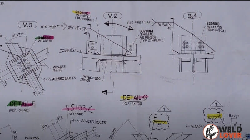
Whenever you have a responsibility to complete a big welding project accurately, then it’s guaranteed that you’ll be shown a welling blueprint. This blueprint shows and guides how to execute the project in time and without any mess. In that circumstance, if you know how to read welding blueprints correctly.
Regardless of the harsh reality, the majority of welders find it hard to read blueprints accurately. The reason for this is that those who cannot interpret welding blueprints are usually those who haven’t taken vocational training. For this reason, only a few welders know how to read welding blueprints, which results in only those welders being able to do their job properly.
When the welder looks at the welding blueprint, it demonstrates how to do the project appropriately. To fulfill all the expectations of the blueprint, you need to have an understanding of every ingredient of the welding blueprint.
Contents
Basics of welding blueprints
You will notice three fundamental types of views if you look at your standard welding blueprints. These views will be of the right, top, and front sides. You will also find different types of welding symbols on a particular area of the diagram. Moreover, these symbols reveal the kind of work that needs to be done to execute the project. So let’s start digging deep into each type of view and symbol.
Welding symbols’ Fundamentals
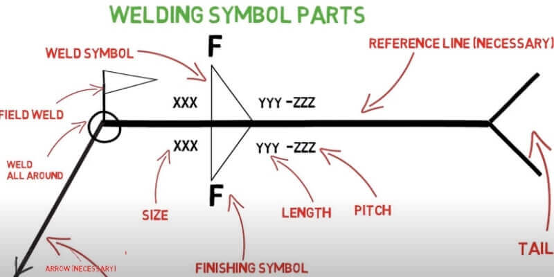
Welding symbols are portrayed with a particular pattern which indicates the type of weld to be created and its direction. Every emblem you look at in the welding blueprint must have an arrowhead; it refers to the area where you have to make a weld.
The arrowhead is joined with a line called line header, which is further linked with a horizontal reference line. Moreover, an arrowhead can be pointed upward or downward, which suggests where to create a weld.
Ultimately, there comes a tail at the other end of the horizontal line. Besides, the tail may contain various forks, which point off in varied directions. This type of tail possesses special instructions for welders.![]()
Other than that, if you see the midpoint of the reference line, you will notice a geometric structure or parallel lines. They indicate what type of weld you have to make on a metal frame. Despite the fact that more than a dozen types of weld symbols are available, you do not need to worry about getting confused with them.
Pay full attention to the placement of the symbols on the reference line when reading the welding drawings. If the symbol of the weld is under the reference line of the diagram, then you have to make a weld on the arrow side of the joint.
Whereas, if the symbol is above the reference line, then you have to make a weld on the opposing side where the arrow points off. You have to weld on both sides of the joint if the symbol exists on both above and below the reference line.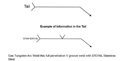
Lots of welding symbols are there to help you discriminate between varieties of welding so you can use them in your projects. For instance, the “V” symbol indicates you have to perform V shape welding, and the “||” symbol says a square weld is required.
As above -mentioned symbols are just examples; there are so many that’s why welders have to put some time into memorizing all of them and their differences. You can make a print of all these symbols and put this print on the wall, which makes it easy for you to remember their meaning.
After memorizing the basic welding blueprint symbols, you now progress toward the next step to understand complex characters that are not very popular.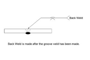
Useful Links:
 What are the components of a welding diagram?
 What are the components of a welding diagram?
When going to decrypt the welding blueprint, it is better to learn the number of components of a welding diagram. Typically, a welding blueprint looks like a jumble of lines, but there are six components in the welding diagram.
- Revision Blocks
- Drawing Numbers
- Dash Numbers and Reference Numbers
- Bill of Material
- Title Blocks
- Scale
Every component of a welding blueprint is crucial for executing the work correctly, so it is essential for the welder to every element of the welding blueprint.
-
Revision Blocks
Nothing is eternal similar to when welding; many things need to be changed in a welding diagram to be written on the blueprint as well. That’s for what revision block exists. You can document every change you made in the project due to some purposes.
-
Drawing Numbers
Similar to a book, a welding blueprint for a mega project can have several pages. So, to ensure that all the pages are arranged and don’t get intermixed, these pages are assigned with a specific number for ease in use.
-
Dash Numbers and Reference Numbers
Both these numbers make sure the process keeps going with proper organization. Dash number is used when the method is proposed on many parts of the blueprint. Similarly, if the process is to be employed on a single portion of the drawing, then you’ll see reference number
-
Bill of Material
The section of the blueprint contains information on all the materials required to do the job. This part of the welding blueprint is very lengthy, as it has data on the sizes and amounts of each material.
-
Title Blocks
This area of the welding diagram includes the title of the project. Moreover, if you are working on a mega project, then it may have information about the phases of the project. In simple words, this part of the blueprint is like the title of a book.
-
Scale
As a welder, you’ll need to review this component of the blueprint to infer the size of the project rather than measuring the blueprint. Moreover, the project size publishes on a little scale to fit the page. In this way, you’ll execute the project with the correct size.
What’s the meaning of the letters on the welding symbols?
Welding blueprint’s symbols’ reading is challenging for untrained welders because they contain letters with hidden information in them. Therefore, if you’re looking to work on large-scale engineering projects, understanding these letters will be very handy. The table below has some important letters and their meaning. Let’s have a look:
A |
Angle of Countersink |
C |
Chipping Finish |
F |
Finish Sign |
G |
Grinding Finish |
L |
Weld’s Length |
M |
Machining Finish |
N |
Number of Points to be Weld |
P |
Pitch of Welds |
R |
Roof Opening; Depth of Weld |
S |
Depth of Preparation; Size of Strength |
T |
Specification Process |
These letters are present with symbols on the welding diagram, which signifies performing a specific weld to complete the project. In addition, these letters also present on their own welding blueprints.
Angels and Dimensions
Understanding the welding symbol’s dimension and angle is crucial because it makes the welding blueprint simpler to read. The blueprint comes with a lot of information, and, in a few lines, it gives a bunch of information. Also, we can use blueprints to communicate width, length, depth, and opening weld
Generally, the width or diameter of the weld is cited on the left of the welding symbol, and the length is always written on the right of the welding symbol and also quoted in inches. In addition to that, welding symbols also tell whether you have to create two welds in opposite directions to each other or not.
The welding symbol also contains a weld’s angle and its root face and root opening dimensions. Again, numbers play a prominent role in identifying angle specifications and weld dept.
These numbers help the welder understand how much leveling of base metals is necessary for performing welding accurately above or under the reference line.
The dimensions that are available below the reference line are for the joint on the arrow’s side. Similarly, the measurements at the top of the reference line are for the joint in the arrow’s opposite direction.
Meanings of Common Symbols
There are lots of symbols on the welding diagram to tell the type of weld. Other than that, these symbols indicate the size of the weld, processing, and finishing data for the project. You will learn some important symbols and their meanings in this segment.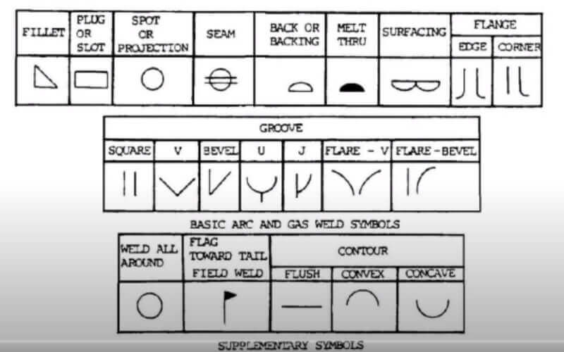
There are three fundamental types of welding symbols.
1. Fillet Welds
The symbol of this weld is nearly a triangle shape at its cross-sectional area. Moreover, the welder can make 90° Corner Joints, T-Joints, and Lap Joints using this welding procedure. However, due to the variation, the shape of the weld isn’t exactly 90 °. Additionally, a little bit of welding filler metal is to be put in on the point of contact of two base metals, and then it melts and forms a joint.
2. Groove Welds
The groove welds are done to make joints that are connected between the edge of two separate sheets or metal frames. Moreover, this distinctive type of weld can be performed in several ways. Other than that, this weld is excellent for joining flat and curved metal sheets. Like fillet weld, it is also perfect for making T-joints and corners. There are different symbols of groove welds because of the distinct shape of the parts that we want to connect.
There are five further classes of groove weld.
- Square Groove Welds
You can perform a square groove weld by creating a partition between two metal frames and edges. If any diameter of space made with this method will be given on the weld symbol
- Bevel Groove Welds
To perform this type of weld, you need to chamfer one side of the joint and leave the other side of the edge in its exact square shape.
- J-Groove Welds
You can perform this weld by bending one metal piece at a concave angle by leaving the other piece of metal in the same square shape.
- V-Groove welds
The process of this type of weld has a resemblance with the square groove method, but the difference is the edges of both metal pieces, which you need to chamfer to accomplish this welding.
- U-Groove Welds
To perform this welding, you have to bend the edges of two metal pieces in a concave shape. After welding finishes, they will form a U shape. This process is similar to V-groove.
- Flare Groove Welds
You can use this type of weld for joining two or more round metal parts. The perfect weld depth is on the left side of the symbol, whereas the depth of the weld appears under parentheses.
3. Slot and Plug Welds
You can apply this welding technique to join the metal sheets and frames that lay over each other. Typically, the sheets have holes in them, that’s why it is mandatory to use welding material to fill these holes, and then it fuses to form a strong bond between metal sheets and frames. The diameter and width of slots and plugs are labeled on the left of the symbol. And the pitch and length of slots and plugs are given on the right of the symbol.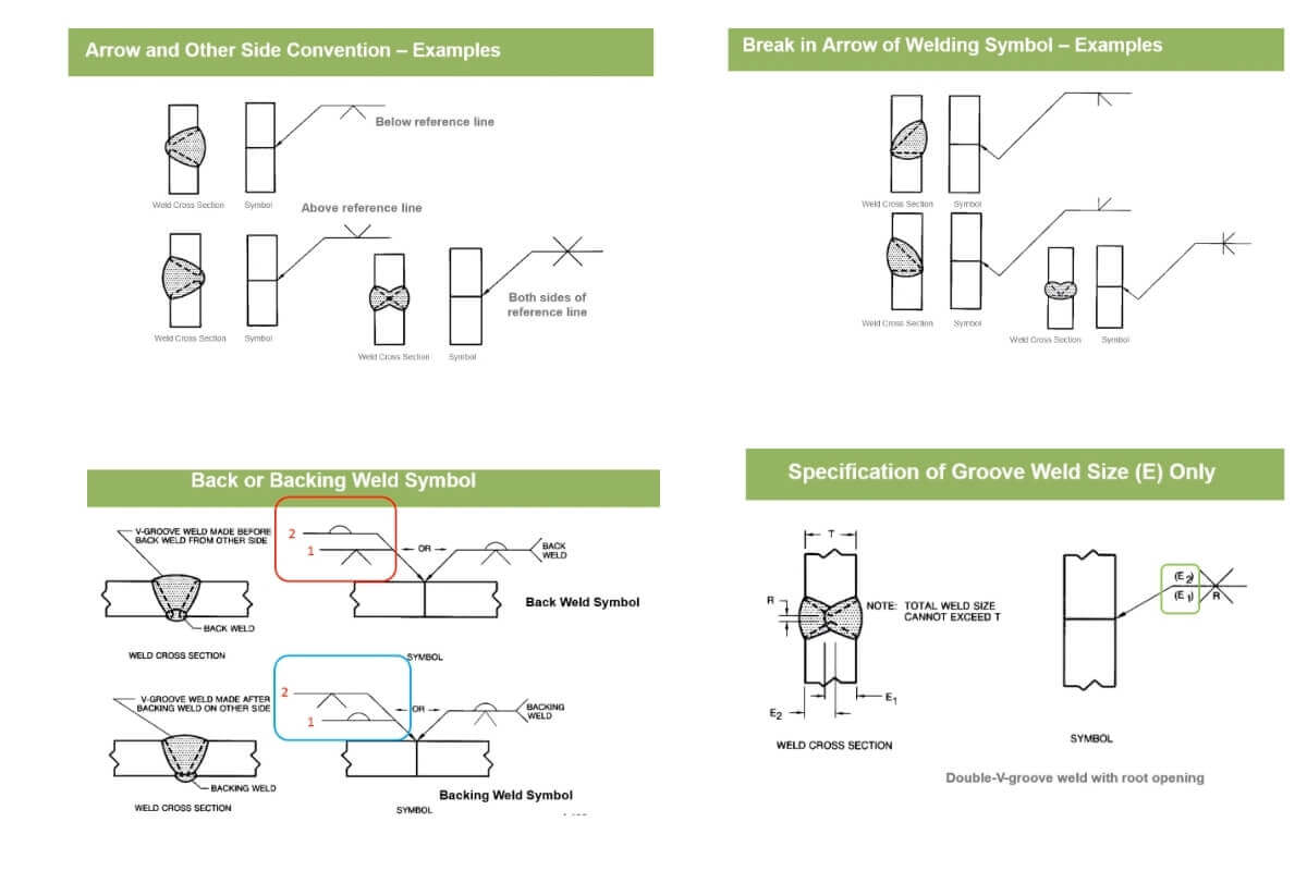
Conclusion:
To conclude, we can say that you must be able to read welding blueprints and symbols as a welder. In this way, you can’t struggle when working on a project. But if you can’t understand the meaning of symbols on the welding blueprint, you will undoubtedly face problems.
You will gain a good understanding of welding blueprints when you read this article.
Moreover, it is good to have a welding symbols chart for memorizing and assistance in work. If you think self-learning isn’t going to work for you, then you should hire a professional trainer.
Useful links:


: Weldlover")
